Product Description
This is the forth in our series of "miniature machine" PLC Trainers, these are real functioning machines and will work just like a production machine.
NOW includes video lessons, a big thanks Tim at www.theautomationstore.com See below for youtube links to the lessons
This will also connect to ANY 24 volt input and relay or 24 volt PLC trainer or a standalone PLC, we will customize any of our trainers to be compatible with all of our mini machines.
Ground shipping only ~ in stock, the PLC is not included.
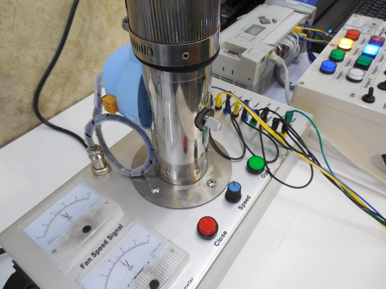
The scope for this trainer to levitate the ball at a given height and the PID will keep the ball at the correct height, the variables are fan speed, manual damper at the top of the tube and at the bottom a electrical damper controlled via the PLC or push buttons.
If the PID is set up correctly it should be able to compensate for the damper position and the more or less airflow and keep the ball at the given height.
These are setup for 0-10vdc, if you want to use current (4-20mA or 0-20mA) we recommend buying a couple of these signal conditioners from AutomationDirect
This is our optional MicroLogix 1100 PLC https://www.plccable.com/custom-allen-bradley-analog-plc-training-micrologix-1100-trainer-for-our-pid-trainer/
What is has:
1 fan assembly that pushes the ball to the top of the tube
1 0-10VDC analog proximity switch on the top of the tube to give the PLC feedback of actual position of the ball
1 0-10VDC meter in showing the signal coming from the PLC to control fan speed
1 0-10VDC meter out going to the PLC as a feedback for position of the ball
1 manual potentiometer for fan speed control, this will be the initial setting then and the input will be the span
1 damper at the bottom of the tube
1 manual open damper switch
1 manual close damper switch
1 manual damper at the top of the tube
We can supply our optional PLC, this one is being controlled by an MicroLogix 1400, you can use any brand of PLC’s with our ‘miniature machine series’, if you have your own you can supply the PLC, just make sure the inputs are 24VDC and the outputs are either DC or relay and has one 0-10v analog in and one 0-10v analog out.
Above is our new updated video on our revised PID Trainer
In this video we are going to be covering our new and updated PID trainer
1st we will be covering the features of the trainer
2nd we will be covering the setup and operation of the trainer
3rd we will be covering the sample PID logic that we supply with the trainer using RSLogix 500
If you are looking for help with just the RSLogix 500 PID and PLC programing logic you can skip forward in the video, we will cover the basics of setup and what you need to know to get your PID working
The goal of the PID trainer is to teach people how PID's work in PLC's, how to tune a PID loop, getting familiar with PID setup screen, cover some math instructions, timers, counters, moves, scaling and much more... With our PID trainer you do not need one of our PLC trainers but you will need you will need a PLC (any brand of PLC) with 2 spare isolated digital 24vdc outputs (either relay or transistor), analog with one analog input (0-10vdc) and one analog output also 0-10vdc, for our video we are using our deluxe micrologix 1400 trainer and a micrologix combination analog I/O expansion card part number 1762-IF2OF2, we could of just use the analog I/O built into the PLC (part number 1766-L32BWAA) but we are using them on our trainer so we needed to add the extra analog I/O card.
First we will cover the features of the trainer... located in the base of the trainer there is a variable speed fan that you will control the speed to make the ball raise and lower, there is a electrical damper at the bottom of the tube, we will use this damper to simulate process fluctuation, there is also a manual damper at the top of the tube that is also for process fluctuation, the lower damper is controlled via the PLC and/or the manual open/close push buttons on the trainer, at the top of the tube there is a positioning proximity switch to give the PLC feedback as to location of the ball height, in our PID we put the setpoint at 50% this means the PID loop will try and keep the ball in the middle of the tube regardless of the position of the upper and lower damper, on the left side of the trainer we have two meters, one is ball height signal and the other is fan speed signal, on the right side of the trainer we have incorporated 2mm banana plugs for easy wiring of the trainer, we also supply the wires you will need to wire the up the PLC to the trainer.
Second is the setup and wiring of the trainer, it runs on standard 120VAC if you are buying this and you are one of our international customers you will need a US to EU power adapter, the trainer has its own 24vdc power supply built in, the top two plugs are your DC to run to your PLC for the digital outputs, the short black wires are all connect as they are your DC common, the damper open is coming from the PLC output and when energized it will open the damper, same with the damper close, these are the yellow wires, blue is the common positive that you are supplying to the PLC here we are showing the other end of the wire, the blue wire being the common positive connected to the relay outputs, the yellow are the outputs sending the voltage back to the PID trainer so when closed/true it will either open the damper or close the damper. Next we have the Fan Control and proximity feedback, this will be the 0-10 volt signal coming from the PID trainer to your PLC for the ball height location and fan control the fan speed you will need to connect the Proximity Switch positive to your analog input, next your PLC analog output will connect to the PID trainer at + FAN Control this will control the fan speed and this will also be the output of the PID in the logic, you will also need to connect the black wire to your analog card for the analog common negative
Now you should have everything wired and now we will start on the logic, continue to the video to review the RSLogix Logic.
Below are the lessons and information videos from www.theautomationstore.com
| PID hardware overview |
|
https://youtu.be/8Yv-aBEZFrc |
| PID Manual Control |
|
https://youtu.be/z_exOMvLG_c |
| PID ON OFF control |
|
https://youtu.be/_7MtYJKbJls |
| PID Basic Studio 5000 Setup |
|
https://youtu.be/Ss81naNK2eo |
| PID Trends | Coming Soon | |
| PID Proportional | Coming Soon | |
| PID Integral | https://youtu.be/7-W-0VE0ZgA |
|
| PID Derivative | Coming Soon | |
| PID Acceleration and deceleration | Coming Soon | |
| PID clamping | Coming Soon | |
| PID troubleshooting | Coming Soon | |
| PID independent variable | Coming Soon | |
| PID Wiring Micro820 to PID Trainer |
|
https://youtu.be/6EPB6bGjZn4 |
| PID Micro820 |
|
https://youtu.be/O-Uify45wZY |
| PID Wiring MIcrologix to PID Trainer |
|
https://youtu.be/RAldLKnyABw |
| PID Micrologix |
|
https://youtu.be/YCNMVE0KHMU |


