Product Description
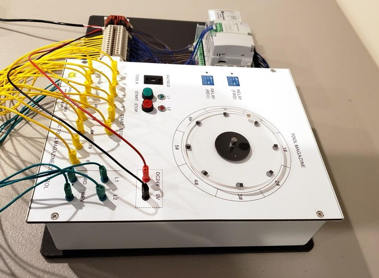
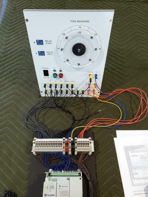
Another great low cost PLC Trainer, this trainer will help you manipulate, run and control DC motors. It includes about 100 pages in a PDF format lesson and exercises for the Allen Bradley Connected Components Workbench (CCW) we are using a 2080-LC20-24QBB PLC and it is included as pictured, wires, terminals, rail... ready to go! These are built to order and normally take 5-7 days.
Learn PLC automated manufacturing process control concepts without large equipment using industrial recognized Allen Bradley Micro800 series hardware and Connected Components Workbench software
A big thanks to Chris at Cuesta College for supplying the lessons and work book for the trainer also for every trainer sold we are donating to Missions to Military https://missionstomilitary.org/ a organization that Chris wanted to sponsor with this project
Lab Designer:
Chris Akelian
Instructor of Engineering Technology and Computer Science
Cuesta College
San Luis Obispo, CA 93403
For our video on the trainer click here on our YouTube channel https://www.youtube.com/watch?v=jLRdTMY86w8
INTRODUCTION
This lab work is intended to help students understand the PLC programming needed to automate a CNC process using the Industrial Concepts CNC Tool Magazine Control Unit as the basis for training. This lab work helps answer the question of how to provide realistic industrial training to college and vocational level students in electrical technology-based curriculums. The importance of answering this question is fundamental to the success of many industries that require qualified engineers and technicians in the automation fields. The lab work becomes progressively more complex so that engineering level tasks are needed to fully automate the process (however, implementing the process is given with step-by-step procedures such that vocational students can get it running with needing engineering courses).
In general, the CNC Tool Magazine Control Unit provides training in sequential process control using motors and sensors. However, it is not classical CNC programming using m and g codes to automate 2- and 3-dimensional fabrication using lathe and mill operations. The training application is for a Pick and Place Tool Magazine operation, and simulates part pickup from any of 8 positions and placement to any one of those same positions. The unit allows training in accepting user defined program sequences so that multiple Pick and Place operations can form a repeatable process that needs various parts from different bins.
Due to common limitations of PLC input and output points the CNC Tool Magazine Control Unit attempts to minimize inputs and outputs, thus generates interesting methods needed for user interaction to operate and program it. This lab uses the Allen Bradley Micro 820-QBB PLC and Connected Components Workbench programming software as the basis for the lab procedures, and is not intended as an independent course on those topics; however, introduces concepts such that students may learn many introductory concepts. Having a background in programming languages is big benefit to understand Function Block programming which is used heavily to simplify the ladder logic programming.
The labs assume little background at the beginning, but as they progress the student is expected to refer back to previously shown concepts as needed. The programming of the Function Blocks is given in Structured Text, and can be typed, or copied from the APPENDIX Section A if using a pdf file format of the lab manual, then pasted into the block to simplify the programming task.
There are 6 labs total that build to a fully automated application in phases. Each lab has an independent result to increase the capability of the trainer to support automated pick and place tasks. At the end of each lab are student exercises to either increase the understanding of the program operation, or to challenge advanced students to modify or increase the program capability.
Learning Objectives
Lab1 Start and Stop operation
• Investigate a Start/Stop Latching circuit
• Create a ladder logic diagram for the latching circuit
• Control lights and motor operation
Lab2 Reciprocating Pick and Place operation
• Utilize part location sensors for pick and place detection
• Discuss reciprocating automation
• Implement a ladder logic reciprocating latching circuit
• Modify the circuit to detect tool positions
Lab3 User Selectable tool positions for the Pick and Place operation
• Create function blocks
• Utilize Structured Text to facilitate converting binary sensor inputs to decimal position values
• Utilize Structured Text to read and debounce the BCD switch then convert to decimal values
o Discuss the need for timer operations to debounce the BCD switch
• Add the user defined function blocks to the main ladder diagram then test them
• Implement the function block outputs to create a selectable pick and place operation
Lab 4 Detecting the shortest path to a tool
• Discuss an algorithm to determine the shortest path to a tool from any relative position in the tool wheel
• Investigate using the algorithm for motor direction control
• Implement the algorithm in two function blocks then test in a ladder circuit for various positions in the tool wheel
Lab 5 Using an Array to store a sequence of Pick and Place operations
• Create a function block using ladder logic to detect maximum BCD switch values
• Store the maximum user input values into an array
• Investigate Indexing and resetting the array
• Implement the function block for controlling a repeating sequence of pick and place operations
Lab 6 Special Ladder Logic Circuits
• Implement a time delay for the pick or place positions
• Adding a parts counter for inventory monitoring
• Discuss and implement a Cycle Stop circuit
Lab Setup
Equipment Required
• Industrial Concepts (www.plccable.com) CNC Tool Magazine Control Trainer
• Allen Bradley Micro820-QBB PLC (2080-LC20-20QBB) with 2080-IQ4 discrete input plug in module (or an equivalent Micro800 series controller)
• 24VDC Power supply, the one shown in the lab pictures is the Allen Bradley Micro800 power supply meant to go with the Micro800 series PLC’s
• Allen Bradley Connected Components Workbench (CCW) software (free to download)
• Workstation (or laptop) loaded with the CCW software and the ability to configure network settings (depending on your network configuration see APPENDIX Section D)
• Optionally, a switch to link the Workstation to the PLC (the one shown in the lab pictures APPENDIX section E is a Wiwav 5 port industrial switch). This can be substituted with just a cross-over patch cord, or a wireless router.
o If a wireless router is used then the switchport on it can patch the PLC to the workstation (which can be wired or wireless). However, Wireless routers by default use DHCP and automatic assignments centered around a default subnetwork (usually 192.168.0.0 or 192.168.1.0); therefore, some of the configuration steps as outlined in APPENDIX Section B may vary (Also see APPENDIX Section D for network configuration options to connect to the PLC)
• Optionally, an IP detection tool called IP Explorer can be purchased to identify IP addresses that may have been previously set on the PLC, so having it can help you establish initial communications


